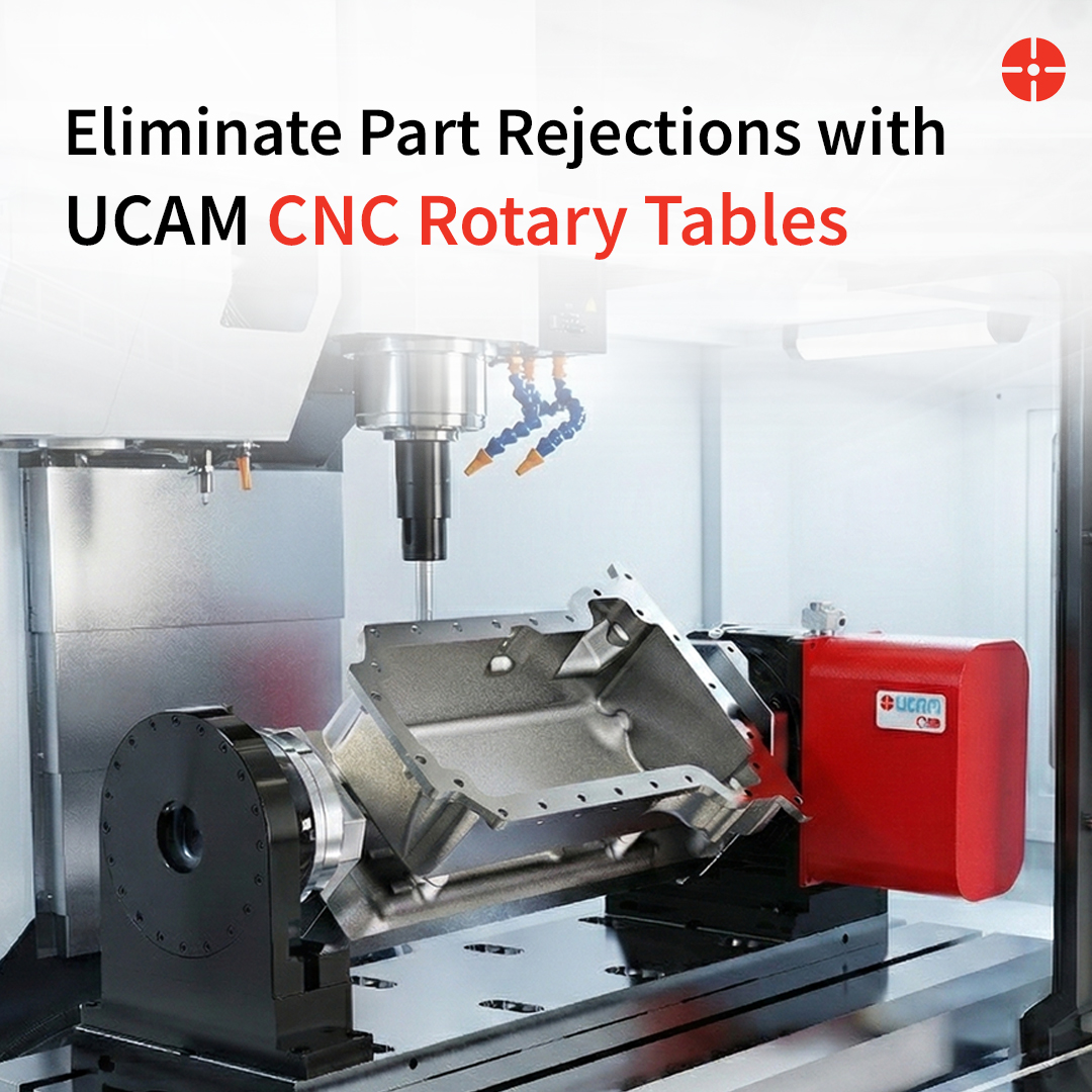
Upgrading a standard 3-axis Vertical Machining Center with a 4th axis Rotary Table is a highly strategic investment for any growing machine shop. By automating part rotation, facilities can completely eliminate manual setups, reduce handling errors, and dramatically increase throughput.
However, selecting the correct CNC Rotary Table requires a careful evaluation of both your component requirements and your machine’s physical limits. VMC operators across the UAE and Gulf region face this exact decision when upgrading their machining capability. Making the wrong choice can lead to workspace interference, inadequate holding power, or integration headaches.
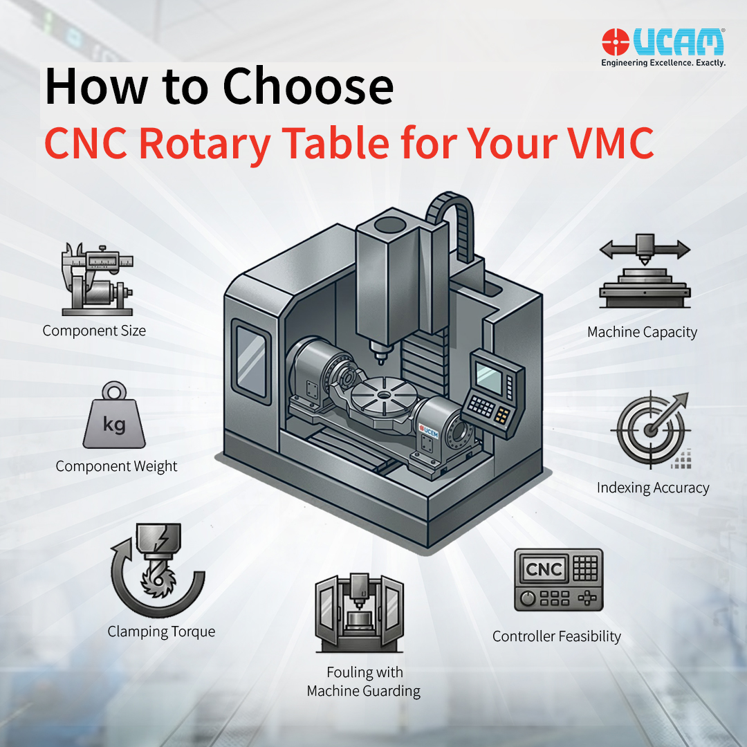
Whether you are evaluating your options before a purchase or comparing technical configurations, this guide breaks down the seven essential factors to consider when choosing a Rotary table for vmc:
1. Component Size
The physical dimensions of your parts dictate the basic geometry of the vmc rotary table you need.
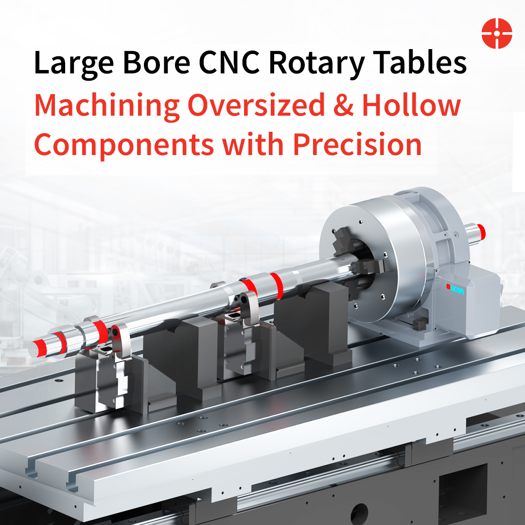
- Swing and Center Height: Verify that the table’s center height accommodates the maximum swing diameter of your component so it clears the machine bed. For larger swing requirements, height blocks can be utilized, provided the load capacity permits.
- Part Length: If you are machining a component vertically and its length exceeds 200 mm, utilizing a tailstock for additional support is highly recommended to prevent deflection.
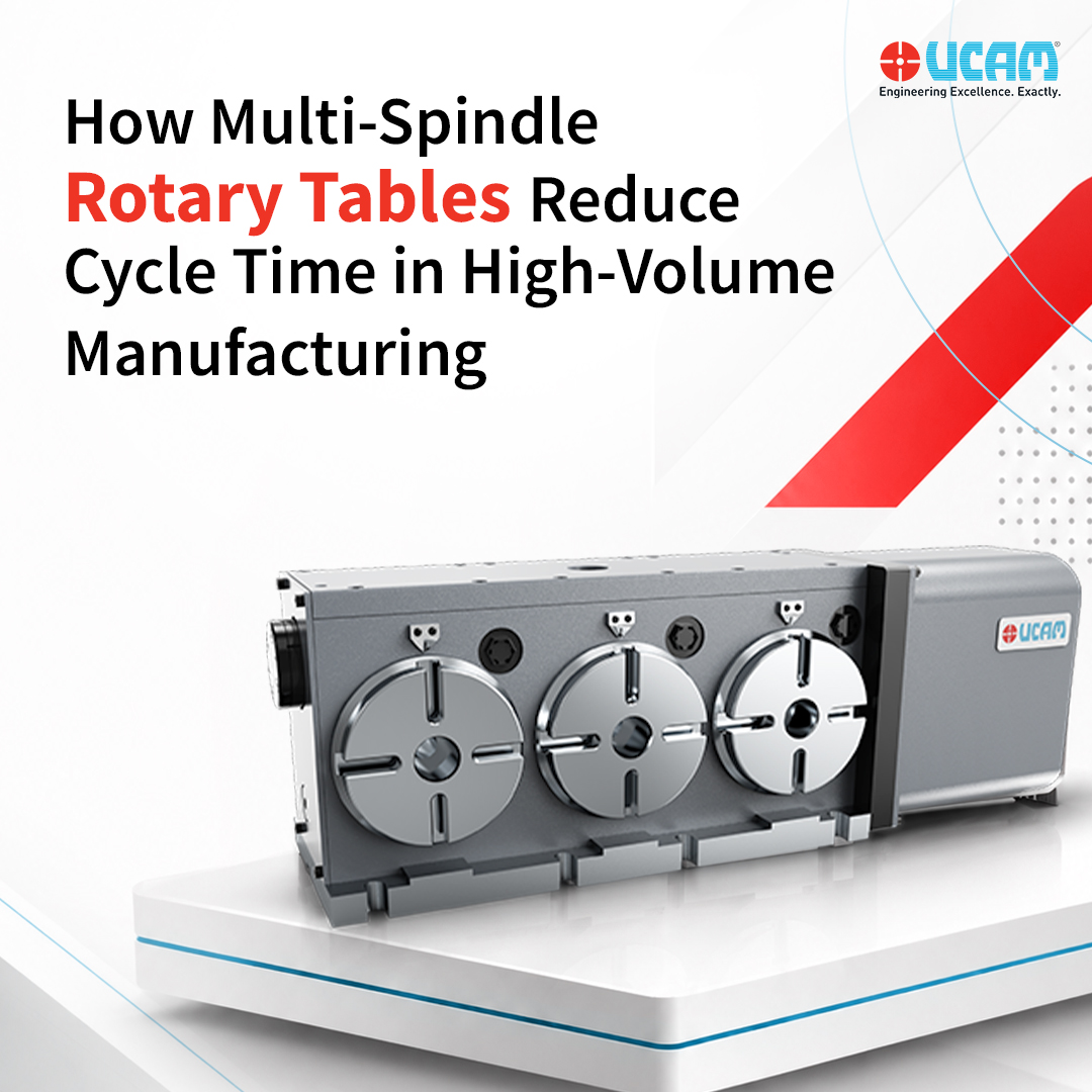
- Multi-Spindle Configurations: If selecting a multi-spindle table, carefully check the center distance between the spindles to ensure your components have adequate clearance to rotate without interference.
2. Component Weight
The table must be physically capable of supporting the combined mass of your setup.
- Total Load: Calculate the total “dead weight” of both the component and the workholding fixture (like a chuck or faceplate). This combined weight must fall safely within the table’s specified load capacity.
- The Tailstock Advantage: Rotary tables typically have a lower load capacity when mounted vertically compared to horizontally. However, applying a tailstock support to a vertically mounted part increases the load capacity to match the horizontal rating.
3. Clamping Torque
When the cutting tool engages the material, it generates rotational force. The table’s braking system must be strong enough to resist this movement.
- Calculating Torque: Machining torque is determined by multiplying the cutting force by the distance from the center of rotation ($ \text{Torque} = \text{Force} \times \text{Distance} $). Ensure your calculated machining torque stays within the table’s maximum clamping capacity.
- Braking Mechanism: Based on the intensity of your cutting forces, you will need to specify either pneumatic (air) clamping for lighter operations or hydraulic fluid clamping for heavy-duty, rigid machining.
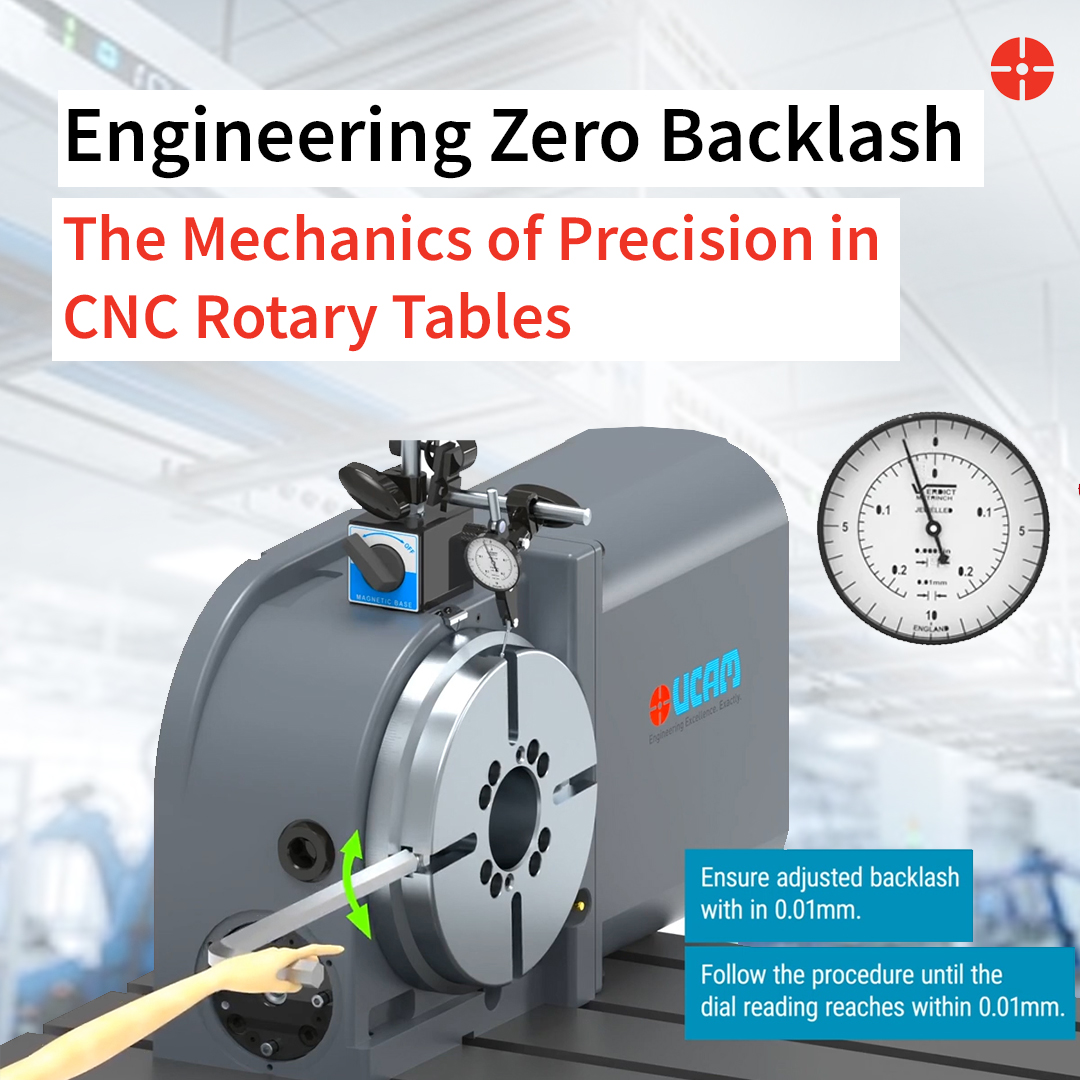
4. Indexing Accuracy
Rotary table precision is generally listed in arc seconds, but machining tolerances are measured in linear units like millimeters or microns.
- Translating the Error: An angular error amplifies the further you machine from the center. You can convert the indexing accuracy of the table (specified in arc seconds) to millimeters at the cutting zone.
- High-Precision Requirements: If your component demands extreme tolerances, standard options may not suffice. Specifying a precision rotary table with an additional high-resolution encoder mounted directly on the table axis guarantees exact positioning (achieving higher accuracy like +/- 5″).
5. Machine Capacity
Your existing VMC must be physically capable of handling the new rotary setup.
- Weight Limits: The total weight of the rotary table, including the workholding and the component, must be within the load capacity of the machine’s bed.
- Working Envelope: Check the machine strokes to ensure that once the table is mounted on the bed, the component falls safely within the reachable machining area.
- Tool Changer Clearance: Ensure there is adequate clearance during an Automatic Tool Change . While changing the tool, the spindle and tooling must not foul with the rotary table assembly.
6. Fouling with Machine Guarding
A rotary assembly takes up considerable space on the machine bed, making clearance checks vital.
- Interference Checks: Once the table is located on the center tenon slot of the machine bed, check for fouling. Verify that the table’s sheet metal guard does not collide with the VMC’s internal machine guards when the machine table is moved to its extreme limits.
- Alternative Configurations: If interference occurs, you can opt for a “Rear Motor” mounting configuration, provided there is sufficient space between the machine table and the machine sheet guard when the table is positioned at the extreme right-hand side.
7. Controller Feasibility
The mechanical hardware must be able to communicate effectively with your CNC controller.
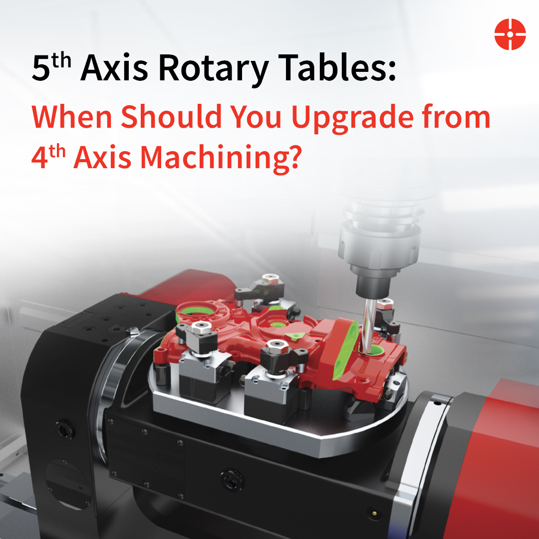
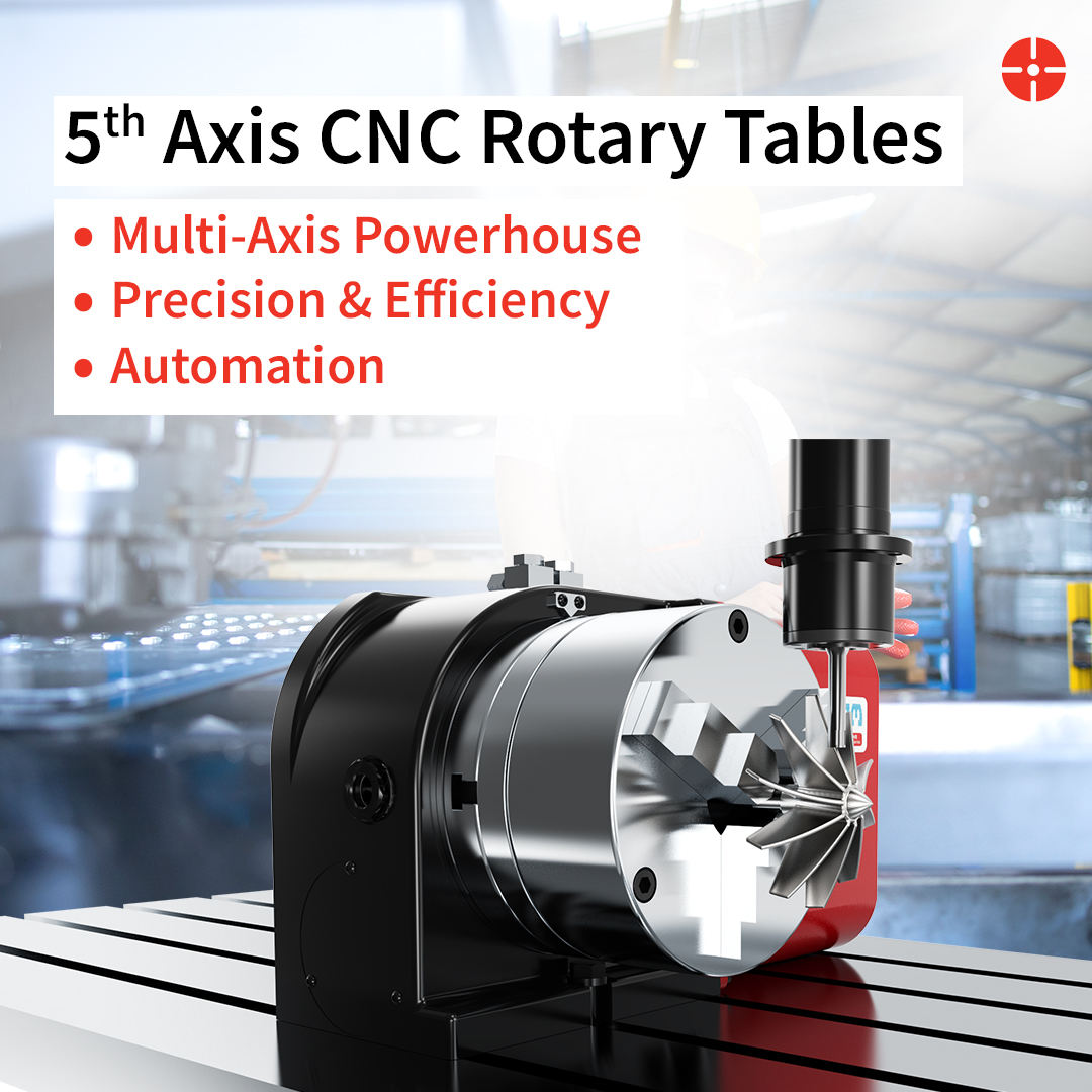
- Axis Capability: Check if your machine’s controller is capable of taking a 4th axis for single-axis tables, and a 4th and 5th axis for two-axis tilting tables.
- Stand-Alone Solutions: If your machine is not capable of handling a 4th axis, you can use a stand-alone controller box. This is feasible provided your component does not need continuous interpolation with machine axes to perform the operation.
- 5th Axis Limitations: In some cases, machine controllers are capable of running 4 regular axes, but the 5th axis can only perform positional indexing rather than continuous cutting.
Conclusion
Transforming your shop floor begins with selecting the optimal workholding technology. Choosing the right CNC Rotary table is a strategic engineering decision that directly impacts your cycle times, part quality, and overall profitability. By carefully matching a rotary setup to your specific workpiece dimensions, tolerance requirements, braking physics, and controller architecture, you guarantee a seamless integration that will reliably accelerate your throughput for years to come.
FAQs
What is the difference between a standard indexer and a true 4th axis rotary table?
A standard indexer simply rotates a part to a set angle and locks it in place for machining (positional indexing), often controlled via a standalone box. A true 4th axis rotary table integrates directly with your machine’s CNC controller, allowing continuous, simultaneous movement alongside the X, Y, and Z axes for complex profiling.
Why should I use a tailstock with my vmc rotary table setup?
When machining a part vertically, any component length over 200 mm creates an unsupported overhang that is highly prone to bending forces and tool chatter. A tailstock supports the free end, drastically increasing rigidity and upgrading the table’s vertical load capacity to match its horizontal rating.
When is it necessary to step up to a precision rotary table?
A precision rotary table equipped with secondary high-resolution encoders is necessary when you are dealing with tight geometric tolerances, such as complex bolt-hole circles or aerospace components. Because angular errors multiply the further you cut from the center, the added encoder acts as a digital scale to eliminate mechanical deviations and maintain sub-micron accuracy.