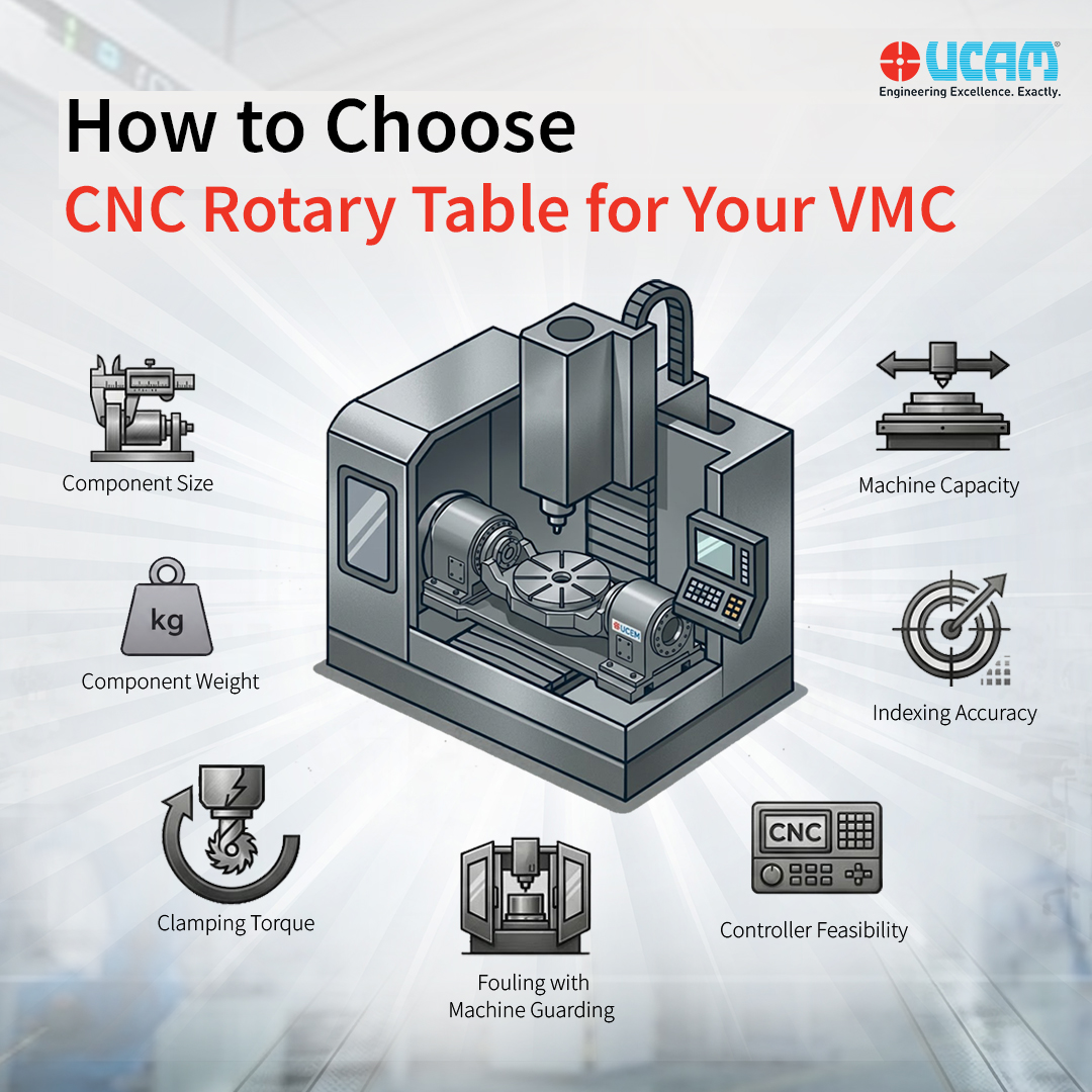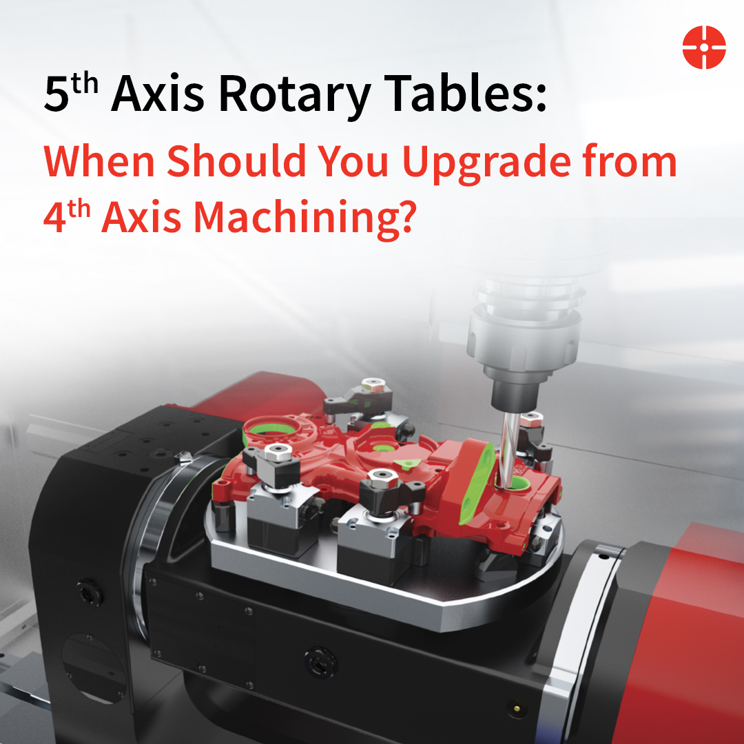
When upgrading a standard Vertical Machining Center (VMC) to handle 4-axis or 5-axis operations, the most critical variable introduced to the machining envelope is the rotary axis.
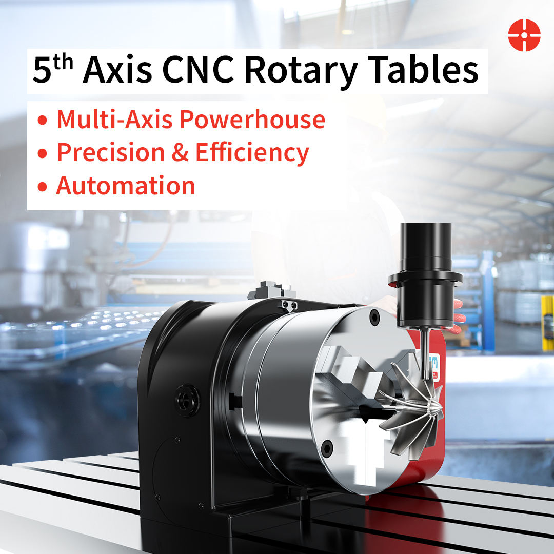
While the concept of adding a CNC Rotary Table to create a fully integrated Rotary Production System is straightforward, the physics of executing it are not. In simultaneous 5-axis machining—where the tool and the workpiece are in constant, dynamic motion—any mechanical deficiency in the rotary table translates directly to the workpiece. The two greatest enemies of this process are backlash and chatter.
At UCAM, our engineering philosophy revolves around eliminating these variables. In this technical deep dive, we explore the internal mechanics required to maintain sub-micron precision under extreme cutting forces.
The Backlash Problem in Rotary Kinematics
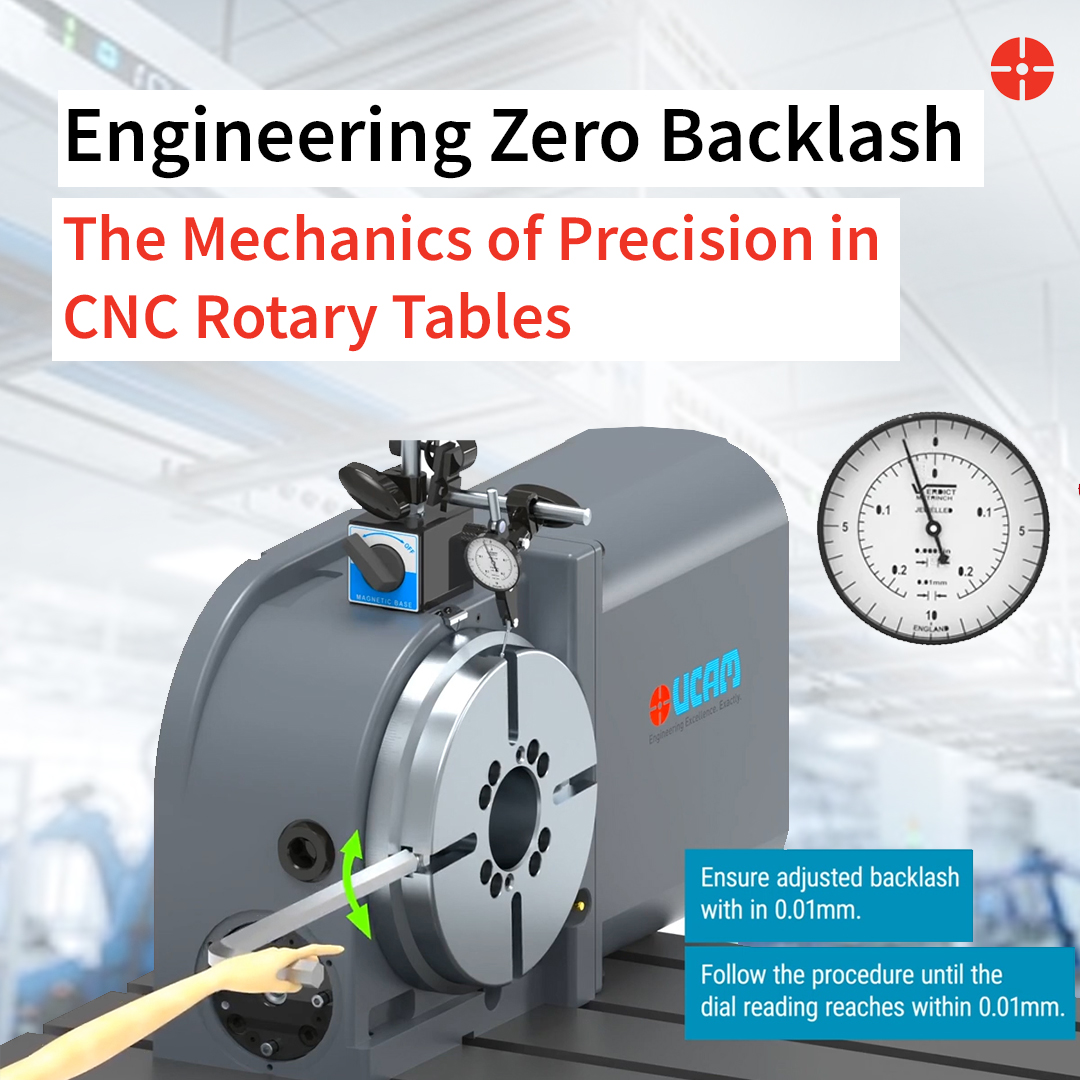
Backlash is the clearance or “play” between mating gear teeth. In a standard rotary table, when the servo motor reverses direction, there is a micro-moment where the drive gear turns, but the driven gear (the platter holding the workpiece) does not move until the gear teeth make contact again.
In single-direction indexing, this can be compensated for via CNC controller software. However, in simultaneous 5-axis machining—such as surfacing an aerospace turbine blade—the table is constantly making micro-reversals. Software compensation is too slow and inaccurate for continuous motion, resulting in faceted surface finishes and dimensional errors.
The UCAM Solution: The Dual-Lead Worm Gear
To achieve true zero-backlash, mechanical clearance must be physically eliminated. While some ultra-high-speed applications are best served by a gearless Direct Drive Rotary Table, UCAM heavily utilizes the Dual-Lead Worm Gear design for its superior torque multiplication and adjustable lifespan in heavy milling operations.
Unlike a standard worm screw, a dual-lead worm screw has a slightly different pitch on the left flank of the thread compared to the right flank. This means the thickness of the worm thread gradually increases from one end to the other.
- Precision Meshing: By precisely moving the worm shaft axially, the thicker portion of the thread is pushed deeper into the mating worm wheel.
- Eliminating Clearance: This action physically closes the gap between the gear teeth, achieving a zero-backlash state.
- Lifecycle Adjustment: As the bronze worm wheel naturally wears down over thousands of hours, standard tables lose accuracy. The UCAM dual-lead design allows maintenance engineers to simply adjust the axial position of the worm screw, restoring factory-level precision without replacing the gear set.
Defeating Chatter: The Physics of Rotary Rigidity
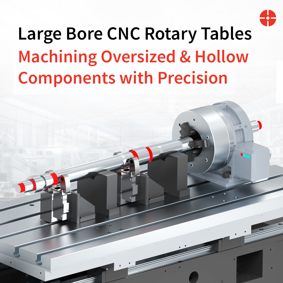
Positioning the workpiece accurately is only half the battle; holding it there against the violent forces of a carbide endmill is the other. This physics challenge remains identical whether you are machining massive pipeline valves on a Large Bore Rotary Table or utilizing a standard CNC Rotary Table for vertical application. If the braking system flexes even a few microns, it induces chatter—a resonant vibration that destroys cutting tools and ruins surface finishes.
High-Torque Hydraulic Clamping vs. Pneumatic Many entry-level rotary tables utilize pneumatic (air-driven) braking systems. Because air is a compressible gas, pneumatic brakes act like a very stiff spring. Under heavy, interrupted cuts, this “spring” compresses slightly, allowing the workpiece to micro-vibrate.
For high-performance applications, UCAM engineers specify Hydraulic Clamping Systems.
- Incompressible Force: Hydraulic fluid cannot be compressed. When the CNC controller signals the table to lock, hydraulic pressure drives a massive clamping sleeve against the brake disc.
- Full-Circumference Locking: Rather than clamping on a single point, advanced tables utilize a sleeve that clamps 360 degrees around the rotary spindle.
The Result:The rotary platter and cast-iron housing fuse into a single, unyielding solid block of metal. This extreme rigidity allows machinists to push heavier feed rates without the risk of chatter.
Real-World Application: The “Done-in-One” Advantage
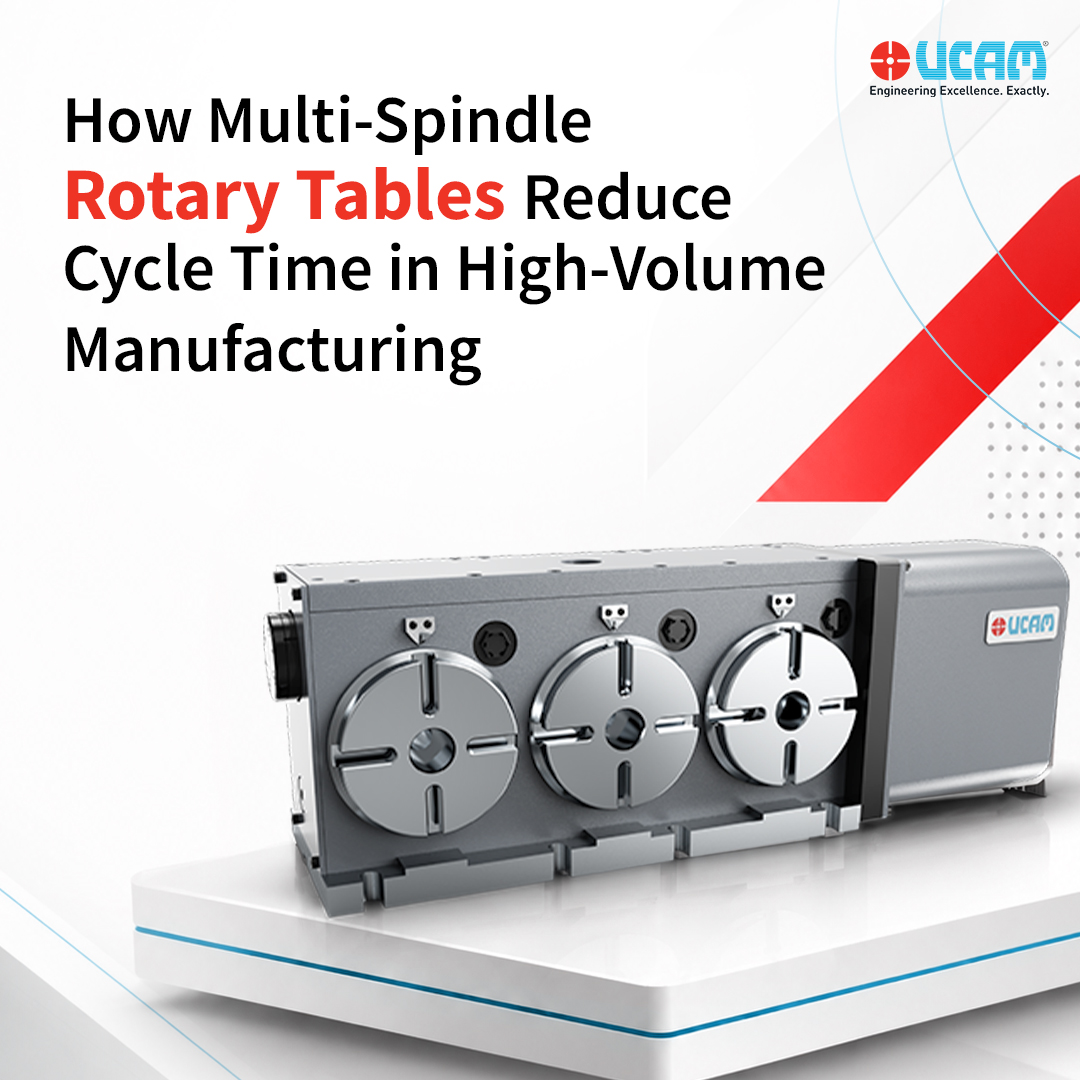
How do these internal mechanics translate to the shop floor? Consider the manufacturing of complex automotive valve bodies or aerospace structural ribs. Depending on the machine architecture, an engineer might specify a CNC Rotary Table for Horizontal Application to ensure optimal chip evacuation, or scale up mass-production throughput using a Multi Spindle Rotary Table.
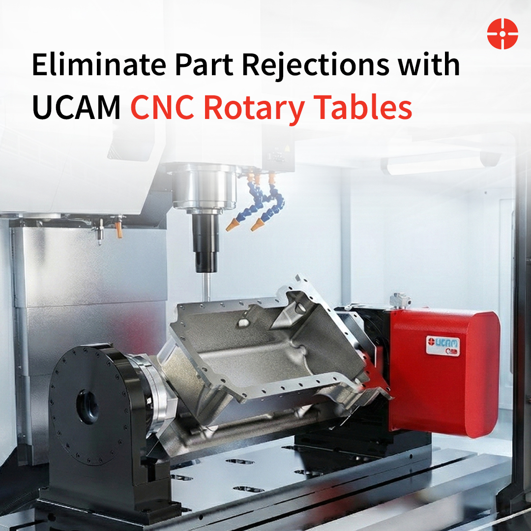
By integrating a UCAM Tilting Rotary Table with high clamping torque and zero backlash, engineers can implement a “done-in-one” machining strategy.
- Without a Rotary table: The part requires 3 to 4 separate setups. Each time the operator unclamps and reclamps the part, a stack-up error of 0.01mm to 0.02mm is introduced.
- With a UCAM Rotary table: The part is fixtured once. The table rotates and tilts to expose five distinct faces to the spindle. Because the dual-lead worm gear maintains exact positional accuracy, and the hydraulic brake prevents deflection, the geometric relationship between all five faces is held to strict aerospace tolerances.
Conclusion: Designing for the Extremes
A CNC rotary table should not be the weak link in your machining center; it should be the anchor. By understanding the mechanical realities of backlash and clamping rigidity, production engineers can make informed decisions when upgrading their CNC capabilities.
At UCAM, we design our rotary solutions for the extremes—because in smart manufacturing, there is no room for lost motion.
FAQs
How often does a dual-lead worm gear need to be adjusted for backlash?
This depends entirely on the duty cycle and the cutting loads. For heavy, continuous milling, an annual inspection is recommended. The adjustment process itself is straightforward and brings the table back to original factory tolerances, significantly extending the table’s ROI.
Can a CNC controller compensate for rotary table backlash automatically?
Yes, most modern CNC controls have a parameter for backlash compensation. However, this only works well for static indexing (positioning the part and locking it). For continuous simultaneous multi-axis machining, mechanical zero-backlash (like UCAM’s dual-lead system) is required, as software cannot predict dynamic cutting forces.
Is a roller cam rotary table better than a worm gear table?
Both have distinct advantages. Roller cam tables use rolling friction, offering high speeds and zero backlash, making them excellent for light-duty, high-volume parts (like electronics housings). Worm gear tables offer significantly higher driving torque and natural resistance to back-driving, making them superior for heavy milling, aerospace alloys, and large-swing components.