
 10 October 2026
 17
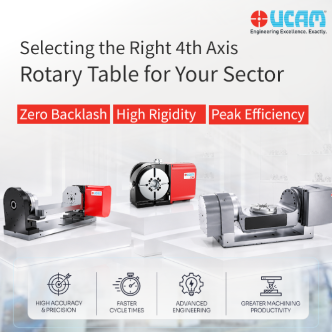
17In precision component machining, integrating a CNC Rotary Table is one of the most effective ways to elevate your shop floor’s capabilities. However, selecting the right rotary system involves more than just matching motor specifications to your CNC controller. One of the most critical engineering decisions a production team must make is determining the optimal rotary table mounting orientation.
The choice between a horizontal vs vertical rotary table setup dictates how the workpiece interacts with the machine spindle, how gravity impacts the bearings, and ultimately, what types of components your facility can successfully manufacture. For export-oriented manufacturers—whether supplying domestic supply chains or serving demanding customers in the UAE and broader Middle East—evaluating mounting orientation based on strict production requirements is a critical step in securing high-margin, tight-tolerance contracts.
Here is a definitive engineering guide to choosing the right configuration for your specific manufacturing challenges.
Vertical Mounting: The Multi-Sided Machining Standard
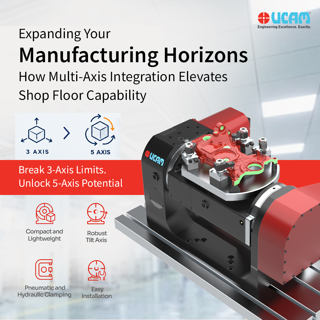
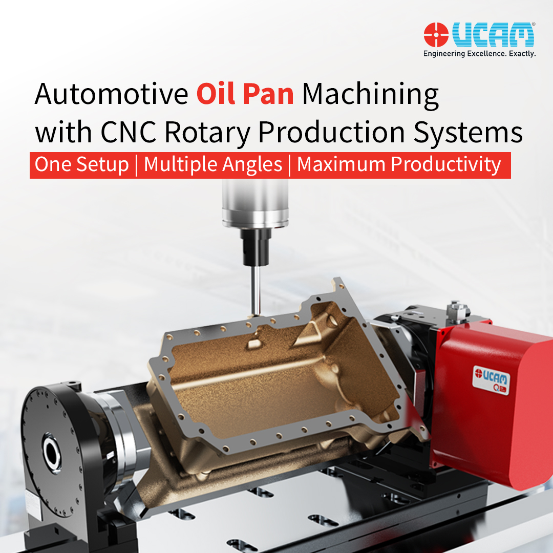
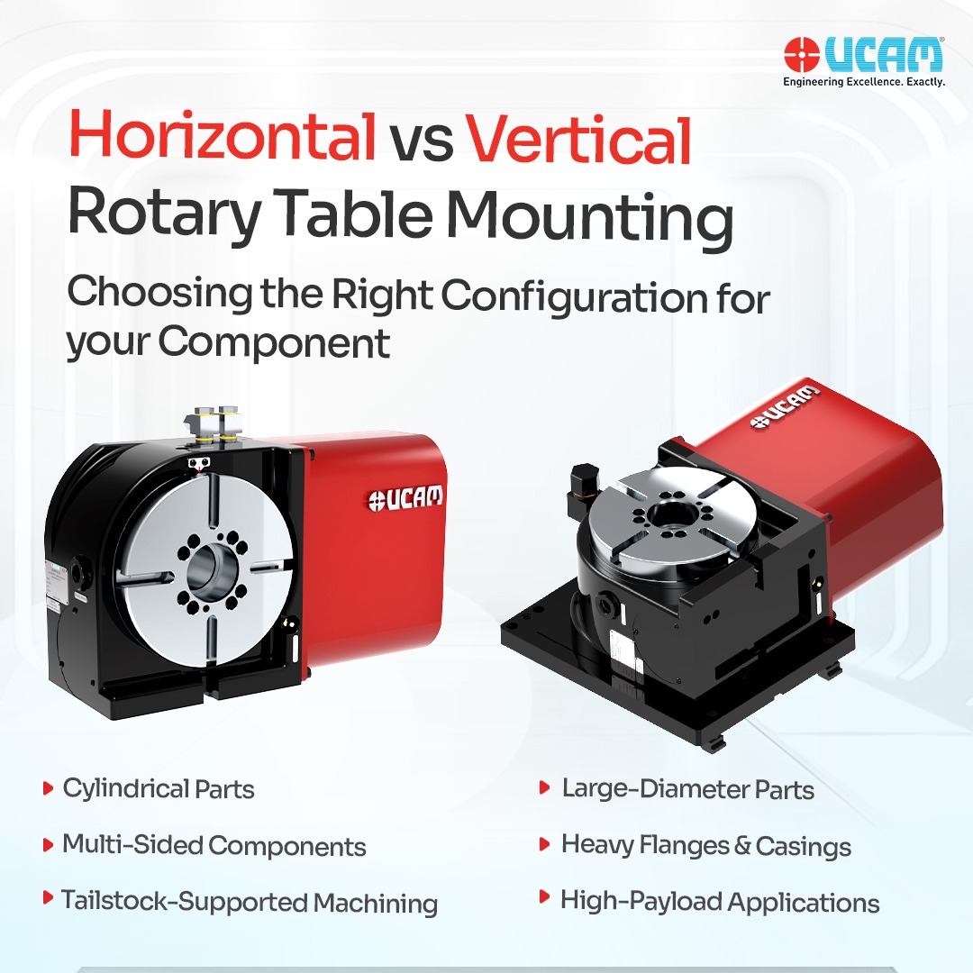
In a vertical mounting configuration, the rotary table is bolted to the machine bed so that its faceplate stands vertically (perpendicular to the machine table). The axis of rotation is parallel to the machine bed, transforming the setup into a standard 4th-axis configuration.
Ideal Component Profiles
Vertical mounting is the go-to configuration for component machining that requires access to multiple sides of a part in a single setup. It is ideal for:
- Cylindrical Parts: Drive shafts, aerospace cylinders, and complex hydraulic spools.
- Multi-Sided Prismatic Parts: Valve bodies and manifolds where the spindle needs to drill or mill intersecting features at various angles around the part’s circumference.
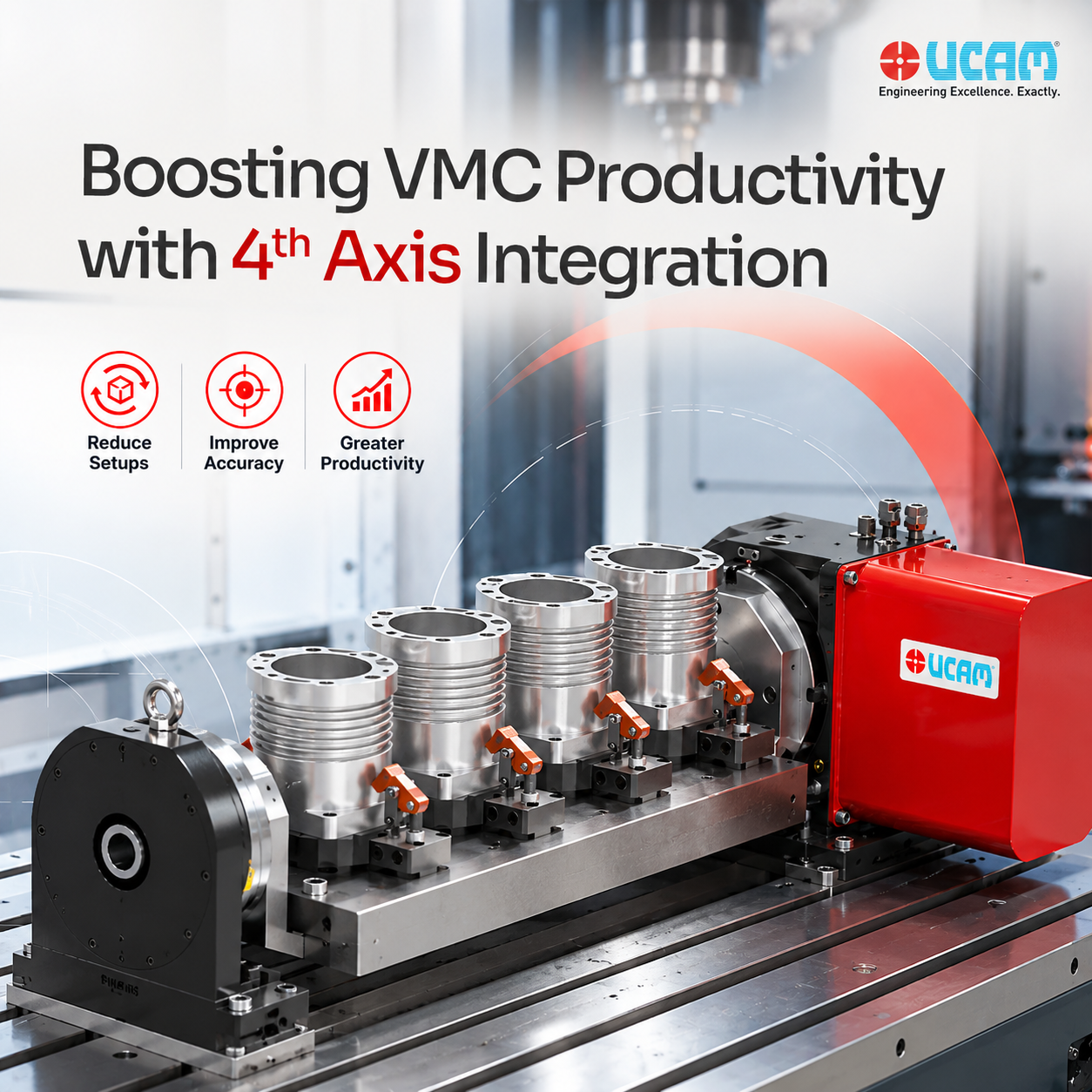
- Trunnion Fixture Setups: Mounting a tombstone between the rotary table and a support bridge to machine multiple small-to-medium parts in a single, high-volume batch.
Engineering Considerations: The Role of Tailstock Support
When mounting vertically, gravity and cutting forces act perpendicular to the axis of rotation. If a long component is chucked only to the rotary faceplate, the weight of the part—combined with the downward thrust of the milling cutter—creates a severe cantilever effect.
To prevent the part from bending or introducing micro-vibrations (chatter), vertical setups handling long or heavy workpieces require robust tailstock support. Aligning a manual, pneumatic, or hydraulic tailstock opposite the rotary table ensures the workpiece remains perfectly rigid, protecting the rotary table’s internal bearings and guaranteeing geometric accuracy along the entire length of the cut.
Horizontal Mounting: The Superior Payload Performance
In a horizontal mounting configuration, the rotary table is laid flat on the machine bed. The faceplate is parallel to the machine table, and it rotates around the vertical Z-axis.
Ideal Component Profiles
Horizontal setups are engineered for massive, wide, and heavy components where multi-axis rotation is required to access a circular bolt pattern or a continuous radial profile. It is the absolute standard for:
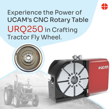
- Large-Diameter Discs: Commercial automotive flywheels, slewing rings, and large gear blanks.
- Heavy Flanges & Casings: Massive energy sector valves and pump housings.
- Rotary Milling: Interpolating large circular pockets or continuous OD/ID (outer/inner diameter) profiles on heavy castings.
Engineering Considerations: Maximizing Load Capacity
The primary engineering advantage of a horizontal setup is how it manages extreme weight. In this configuration, the workpiece’s center of gravity drives downward, pushing directly into the rotary table’s axial thrust bearings.
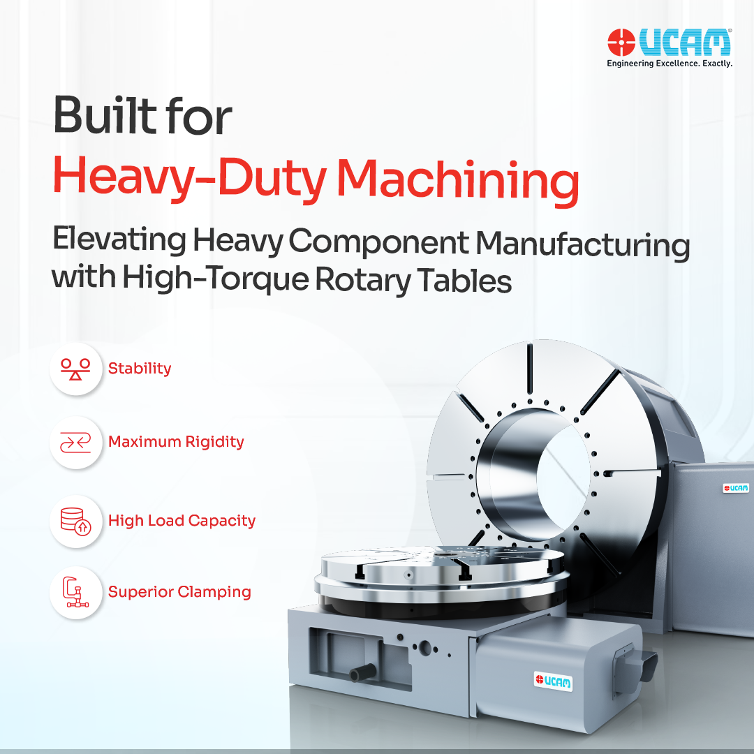
Because the weight is fully supported by the flat table rather than hanging off the side, the load capacity in a horizontal configuration is dramatically higher than in a vertical setup. High-torque UCAM Rotary Tables utilized in horizontal configurations can easily manage multi-ton payloads. The flat orientation neutralizes the cantilever effect, allowing the machine to execute aggressive face-milling and deep-hole boring on oversized parts with zero deflection.
How to Choose the Right Configuration
When specifying a rotary table for your Vertical Machining Center (VMC), production engineers should evaluate three primary criteria:
- Center of Gravity & Weight: If the part is long and cylindrical, choose vertical (with a tailstock). If the part is incredibly heavy, flat, and wide, horizontal mounting is mandatory to safely manage the load capacity.
- Spindle Access Requirements: Do you need the spindle to access the side profiles of the part (Vertical)? Or do you need the spindle to access the top face of the part at various indexed angles, such as drilling a massive circular bolt pattern (Horizontal)?
- Z-Axis Clearance: Vertical mounting consumes significant Z-axis daylight because the table, the fixture, and the part stand upright. Horizontal mounting keeps the profile lower to the machine bed, leaving more room for the spindle to retract during automated tool changes.
The UCAM Advantage: Engineered for Versatility
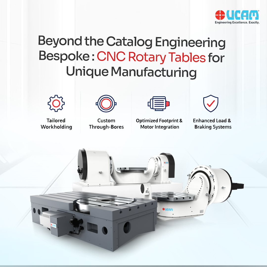
Adapting to shifting production demands is the hallmark of a premier machine shop. Recognizing this, UCAM engineers many of its premium CNC Rotary Tables with dual-mounting capabilities.
Built with precision-ground mounting faces on both the back and the bottom of the iron casting, versatile UCAM models can be easily transitioned from a vertical 4th-axis setup for complex shaft machining to a horizontal setup for heavy flange drilling. Paired with UCAM’s comprehensive range of hydraulic tailstocks and custom workholding solutions, this dual-capability ensures your shop floor is always equipped with the exact rigidity and orientation required to execute flawless, zero-defect manufacturing.
Reach out to us and we will help you find your exact requirement match.
FAQs
Can a single CNC Rotary Table be used for both horizontal and vertical mounting?
Yes. Many industrial-grade Rotary tables, including UCAM’s URX and URH series, are engineered with dual-mounting capabilities. The cast-iron housing features precision-ground bolting surfaces on both the back and the bottom. This allows a facility to mount the table vertically for 4th-axis shaft machining, and later lay it flat horizontally to process heavy circular flanges, maximizing equipment utilization.
At what point is a tailstock strictly necessary for a vertical setup?
A tailstock is required whenever the length and unsupported weight of a workpiece create a cantilever load that exceeds the rotary table’s maximum tilting moment capacity. Without support, radial cutting forces at the far end of the part will induce chatter and accelerate bearing wear. Applying a pneumatic or hydraulic tailstock converts the setup into a fully supported beam, effectively doubling the table’s vertical load capacity to match its horizontal rating.
Does mounting a table horizontally to handle heavier payloads compromise its indexing accuracy?
No. High-quality rotary tables utilize pre-loaded axial-radial cross-roller bearings that distribute massive downward thrust evenly across a broad surface area. Furthermore, once the table rotates to its programmed position, high-pressure hydraulic brakes lock the faceplate solid. This ensures that even when supporting multi-ton castings horizontally, the system maintains zero backlash and sub-micron positioning accuracy during heavy metal removal.


 ucam_marketing