 14 November 2026
 16
In advanced manufacturing sectors like aerospace, energy, and medical devices, production engineers are frequently tasked with machining complex, unbalanced components. Standard workholding practices dictate the use of a tailstock to support long or heavy parts, effectively creating a rigid bridge. However, when dealing with asymmetrical part machining—such as offset pump housings, irregular valve bodies, or complex aircraft linkages—the physical geometry of the workpiece often obstructs opposite-end support.
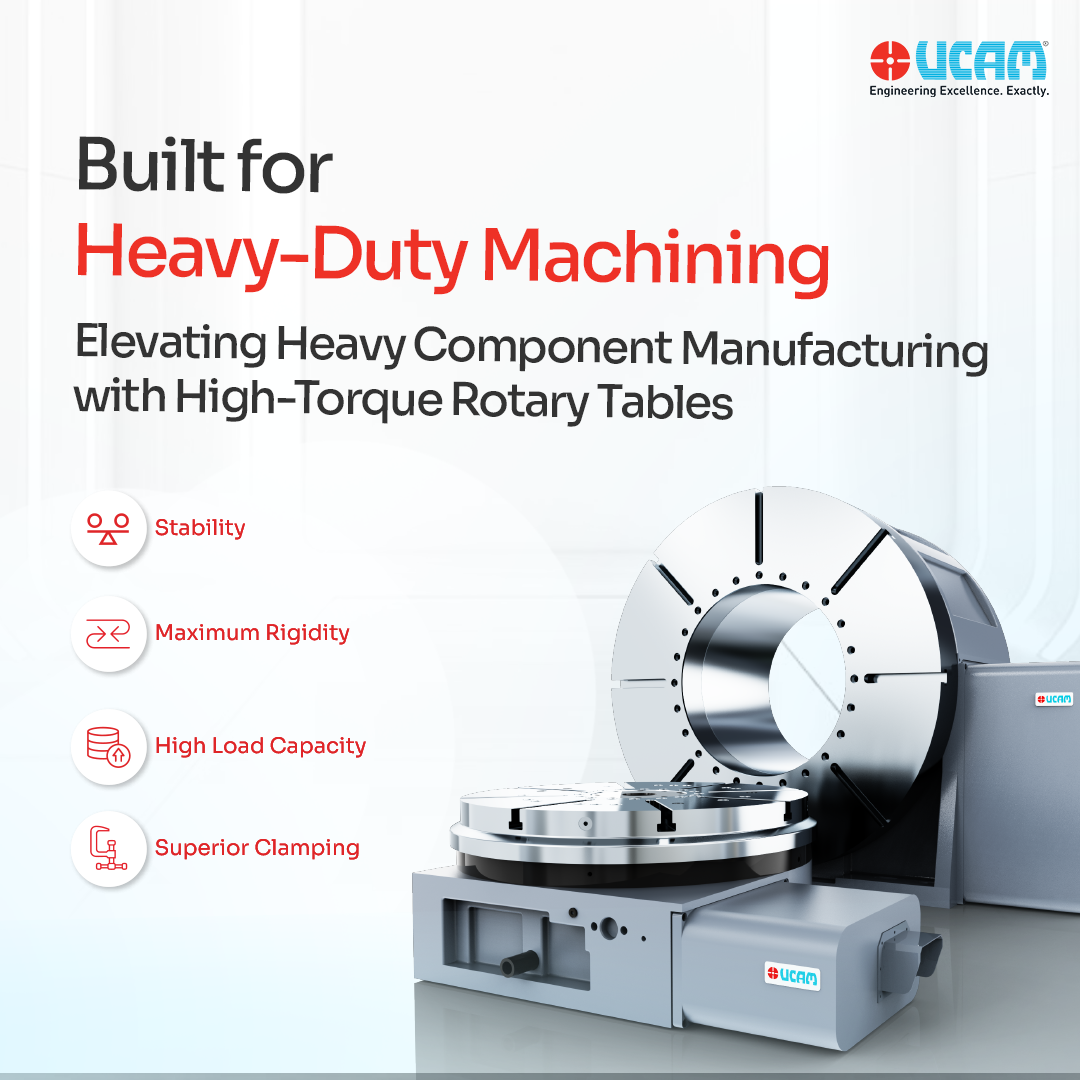
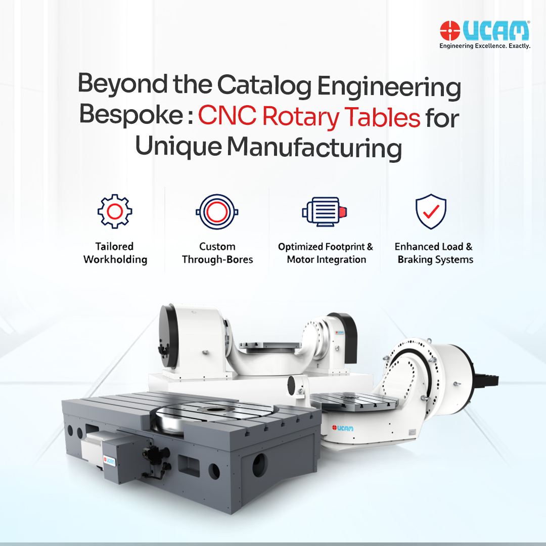
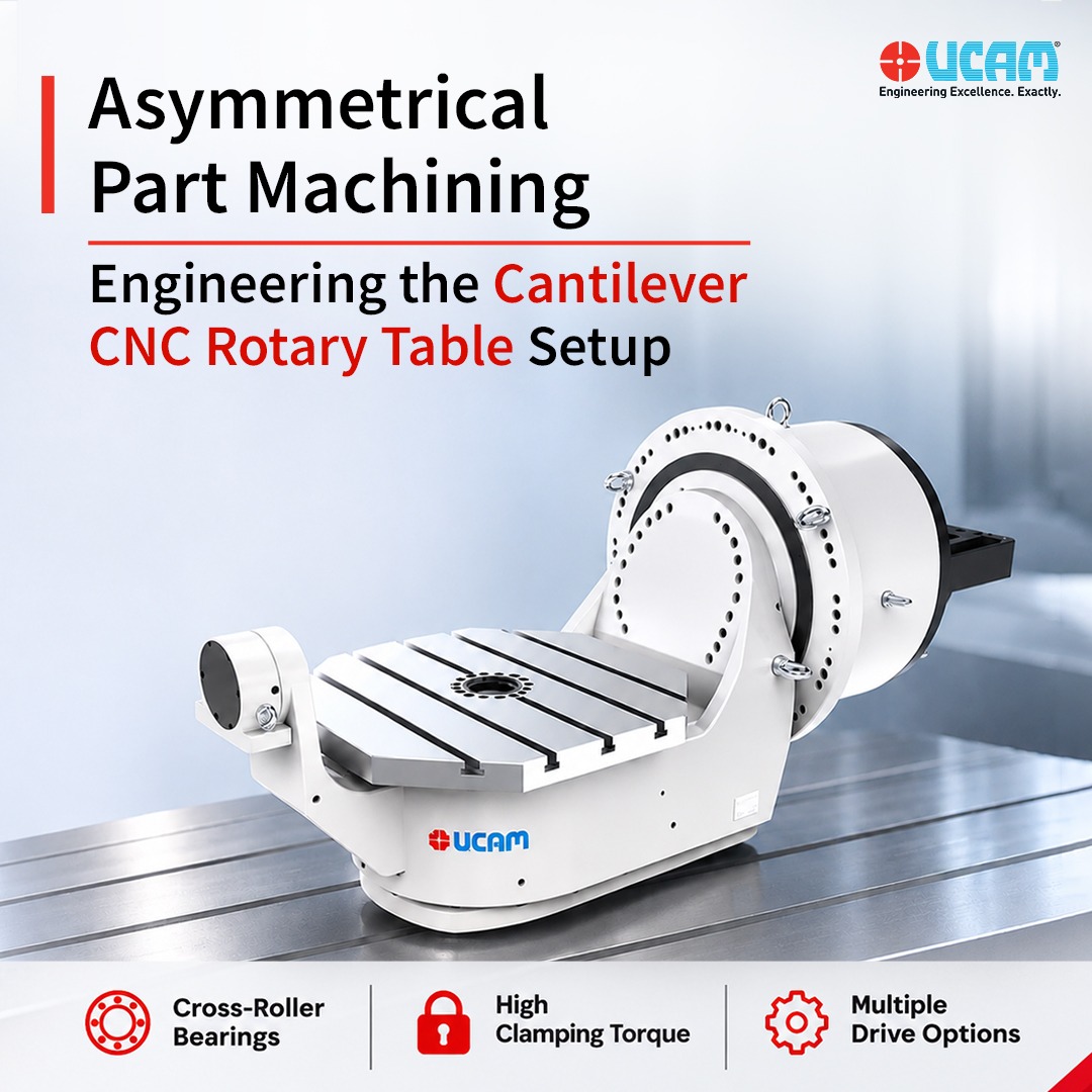
When a tailstock physically cannot be deployed, the workholding must support the entire workpiece from a single side. This introduces the engineering challenge of off-center payload machining. To process these components accurately without catastrophic deflection or tool chatter, manufacturing facilities must specify a highly specialized piece of equipment: the Cantilever CNC Rotary Table.
Here is the engineering breakdown of how cantilever architectures manage extreme tilting moments, and how to specify the correct drive mechanism for your production environment.
The Physics of Off-Center Payload Machining
When a CNC spindle engages the far end of an unsupported, asymmetrical workpiece, the radial cutting force acts as a lever against the rotary table. This generates a severe bending moment (eccentric load). Standard rotary tables will experience microscopic internal flexing under this leverage, multiplying into severe dimensional inaccuracies at the cutting zone.
To counteract this, a cantilever setup requires two foundational mechanical pillars:
- Axial-Radial Cross-Roller Bearings: Standard angular contact bearings cannot resist extreme twisting forces. Premium cantilever tables utilize highly pre-loaded axial-radial cross-roller bearings. In this design, cylindrical rollers are arranged in an alternating, perpendicular crisscross pattern. This allows a single bearing unit to absorb multidirectional forces simultaneously, neutralizing the bending moment and holding the unsupported part perfectly rigid.
- Extreme Braking Friction: When the cutting tool strikes the cantilevered end of the part, it attempts to back-drive or rotate the faceplate. To prevent the part from slipping, the equipment must be a high holding torque CNC table. High-pressure hydraulic clamping systems are mandatory, applying massive friction directly to the axis to lock it into a solid block of iron during heavy metal removal.
Specifying the Drive Mechanism: The UCAM SQ600CT Series
Because asymmetrical parts range from heavy cast-iron energy components to high-speed aluminum aerospace linkages, a one-size-fits-all drive mechanism is insufficient. The UCAM SQ600CT series is engineered specifically for cantilever applications, offering three distinct drive architectures to match the exact physics of the cutting operation.
1. The Heavy-Roughing Standard: Dual Lead Worm Gear Mechanism
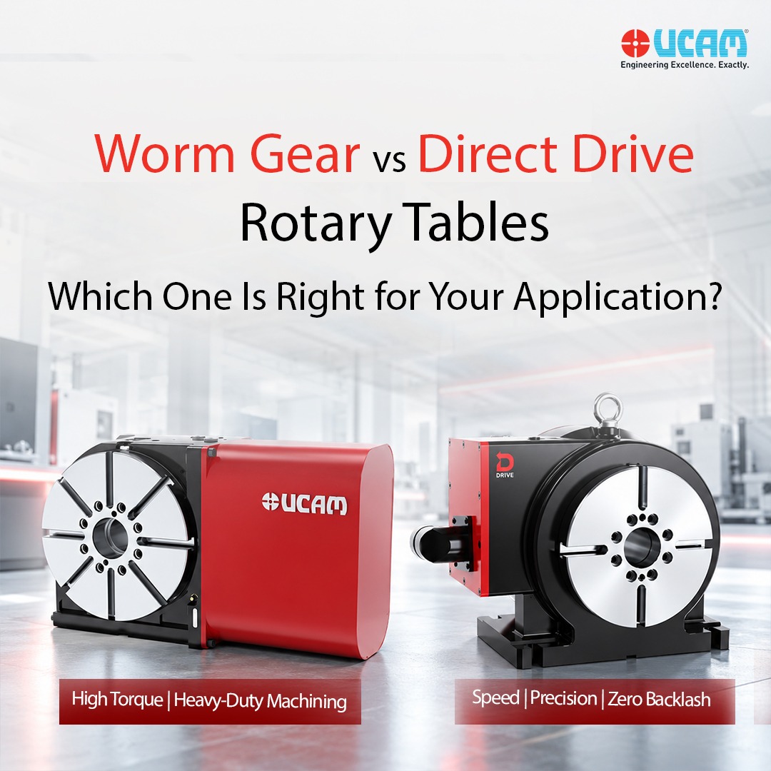
For processing heavy, off-center steel forgings or cast iron, maximizing mechanical advantage is critical. The URH SQ600CT configuration utilizes UCAM’s proprietary dual lead worm gear mechanism on both the rotary and tilt axes. This provides immense torque multiplication to fight gravity on asymmetrical loads. Furthermore, as the gear naturally wears under these extreme loads, the dual-lead design allows maintenance engineers to micro-adjust the gear mesh, permanently restoring the table to zero-backlash factory tolerances.
2. The Hybrid Architecture: Direct Drive Rotary Axis
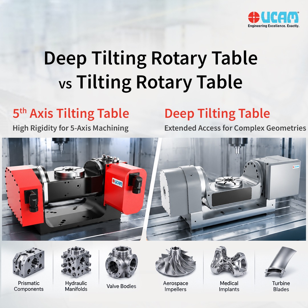
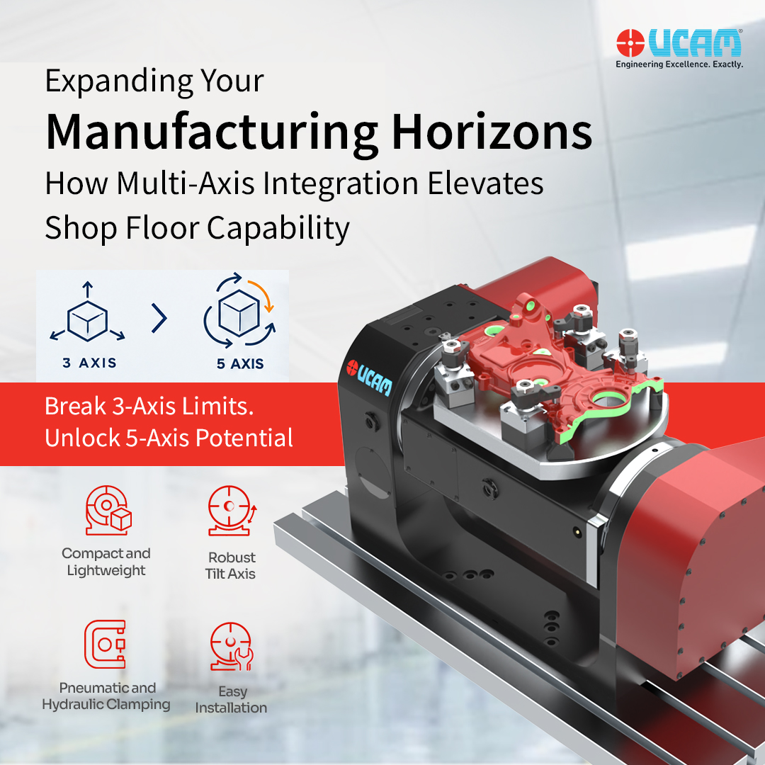
For components that require a balance of aggressive tilting support and high-speed rotational contouring, the URD SQ600CT provides a strategic hybrid solution. This CNC tilting table pairs a heavy-duty worm gear on the tilt axis (A-axis) with a direct drive rotary axis (C-axis). The tilt axis retains the mechanical locking torque required to safely suspend heavy cantilevered loads, while the gearless magnetic torque motor on the rotary axis delivers instantaneous acceleration and ultra-high RPMs to drastically reduce cycle times.
3. Ultimate Precision: Full Direct Drive Rotary Table
When surface finish and geometric perfection are the highest priorities—such as in turbine blade manufacturing or medical implant machining—the UDD SQ600CT configuration is the premier choice. By utilizing torque motors on both axes, this Direct Drive Rotary Table eliminates internal gearing entirely. The result is zero mechanical backlash and zero physical friction, enabling a flawless, continuous 5-axis simultaneous machining setup for complex spatial contouring on unsupported components.
Strategic Manufacturing Integration
Attempting to machine asymmetrical components on standard rotary setups leads to fixture interference, multiple manual setups, and compromised concentricity. By integrating a dedicated Cantilever CNC Rotary Table equipped with pre-loaded cross-roller bearings and extreme hydraulic clamping, manufacturing facilities can process highly irregular parts in a single automated setup. By selecting the correct drive configuration within the UCAM SQ600CT series, production engineers guarantee sub-micron precision and maximum spindle utilization, regardless of the part’s geometric complexity.
FAQs
Why are axial-radial cross-roller bearings required for cantilever machining?
When a workpiece is supported from only one side, machining forces create a severe twisting leverage (eccentric load) on the rotary table. Standard bearings flex under this stress. Axial-radial cross-roller bearings feature alternating, perpendicular rollers that simultaneously absorb forces from all directions. This design neutralizes the off-center leverage, ensuring the faceplate remains completely rigid during heavy cuts.
How does a dual lead worm gear mechanism benefit off-center payloads?
Supporting asymmetrical weights places extreme, continuous stress on the internal drive gears, which can accelerate wear and introduce backlash. A dual lead worm gear mechanism allows engineers to physically micro-adjust the depth of the gear mesh over time. This compensates for any wear, restoring the table to original zero-backlash precision and guaranteeing a long operational lifespan despite the heavy eccentric loads.
When should a facility specify a direct drive rotary axis for a cantilever setup?
A direct drive rotary axis (as found in the URD or UDD SQ600CT configurations) should be specified when the part requires high-speed, continuous 5-axis contouring rather than just heavy positional roughing. Because direct drive motors eliminate gears, they provide strictly zero backlash and instantaneous acceleration, making them ideal for complex aerospace and medical geometries where surface finish and rapid cycle times are paramount.


 ucam_marketing