 24 October 2026
 26
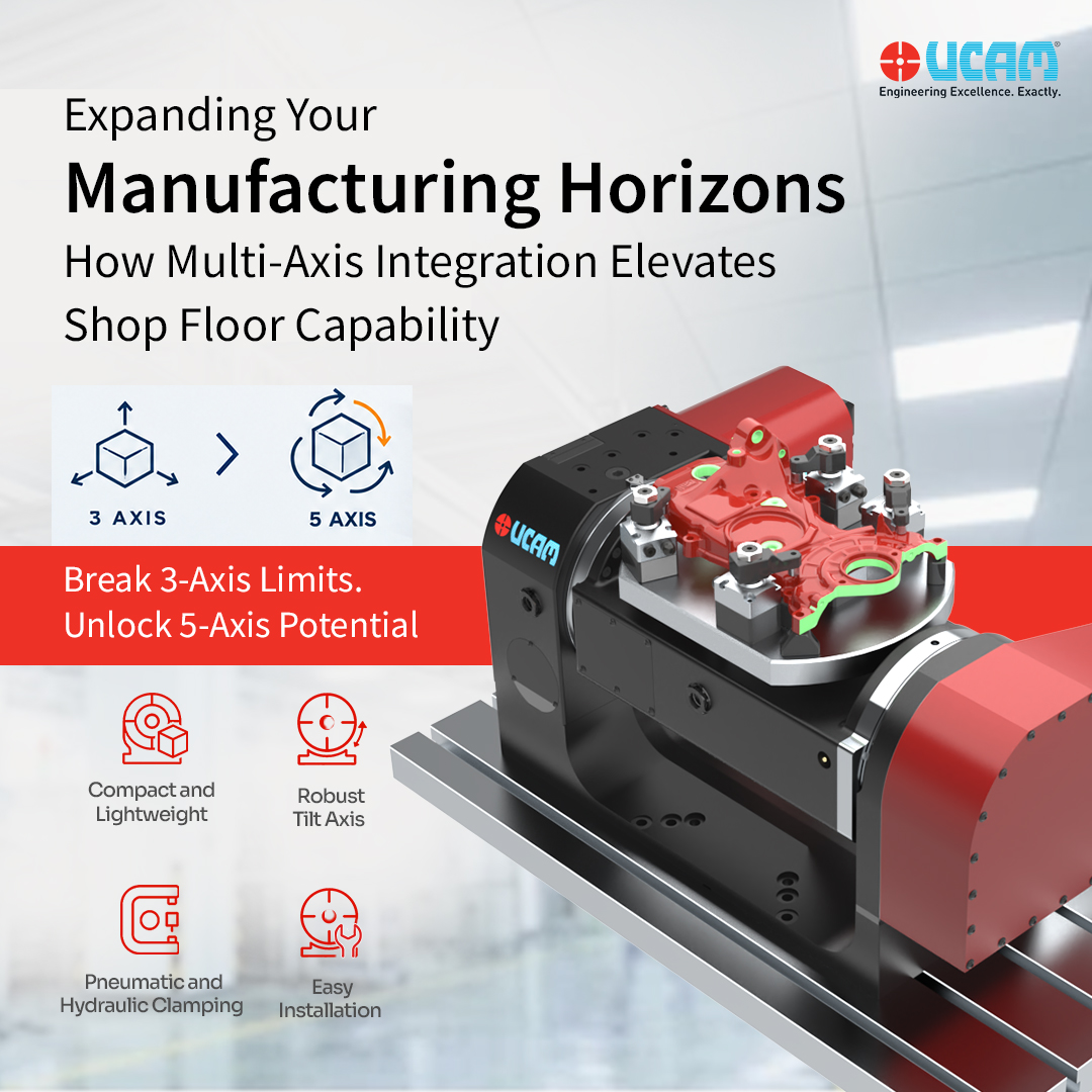
Integrating a CNC Tilting Table into a Vertical Machining Center (VMC) upgrades the machine for simultaneous 5-axis machining or 3+2 positional indexing. This mechanical addition allows manufacturers to process multiple faces of a complex component in a single clamping setup. However, selecting the correct trunnion architecture is a strict engineering requirement based on the physical dimensions of the machine envelope and the geometry of the workpiece.
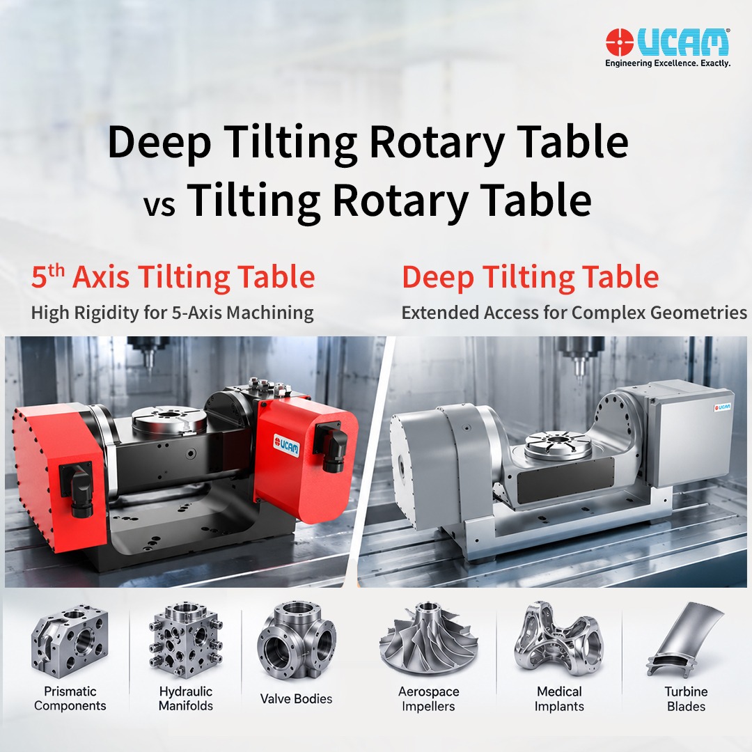
Engineers evaluating a Deep Tilting Rotary Table vs standard Tilting configuration must analyze spindle clearance, required cutting torque, and specific negative-angle access. This technical guide outlines the structural differences and operational parameters of both configurations to ensure correct equipment specification.
Standard Tilting Rotary Tables: Mechanical Architecture
A standard CNC Tilting Rotary Table is constructed to provide multi-sided access to a workpiece while prioritizing maximum structural rigidity. In this configuration, the rotary faceplate is mounted in direct alignment with, or very close to, the centerline of the primary trunnion pivot arms.
Rotary Table Tilting Angle Specifications
The mechanical layout of a standard tilting table typically restricts the tilt axis (the A-axis) to a positive range. The standard rotary table tilting angle operates from 0° (perfectly horizontal) to approximately +110° or +120° past the vertical position.
Operational Rigidity and Product Integration
Because the faceplate sits close to the trunnion centerline, the center of mass remains highly compact. Standard tilting tables provide exceptional dynamic stiffness during heavy metal removal operations. High-pressure hydraulic brakes applied to the tilt axis lock the trunnion securely in place. UCAM’s standard tilting tables utilize this compact architecture to efficiently absorb massive radial thrust generated by large indexable face mills or deep-hole drills without inducing harmonic vibration or tool chatter.
Target Applications This configuration is specified for prismatic parts, multi-sided hydraulic manifolds, and heavy valve bodies. It is the standard choice for 5-face machining processes that do not involve severe undercuts or negative draft angles.
Deep Tilting Rotary Tables: Mechanical Architecture
A CNC Deep Tilting Rotary Table is specifically engineered to resolve physical limitations regarding Z-axis clearance and negative-angle spindle access.
Design Modifications and Tilting Angles
The fundamental difference in a deep tilting configuration is the geometry of the trunnion cradle. Deep tilting tables utilize a “drop-center” design, where the rotary faceplate is positioned significantly lower than the tilt axis centerline. In addition, the motor housings and support arms are cast with a swept-back or contoured profile. This modified physical architecture permits the table to achieve extreme negative tilting angles, frequently reaching -30° or more, without the table housing colliding with the machine spindle housing.
Clearance, Spindle Access, and Product Integration
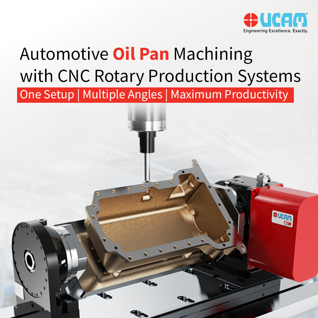
The drop-center layout provides unimpeded geometric access. When machining components with severe undercuts, the cutting tool must approach the workpiece from below the standard horizon line. A deep tilting table drops the workpiece into a recessed cradle, allowing the spindle head to navigate completely around and under the part for continuous 5-axis machining.
UCAM engineers the URH-DT Series specifically for these requirements. The drop-center design accommodates large components without sacrificing vertical machine stroke. Furthermore, to compensate for the shifted center of gravity, models like the URH-500DT deliver up to 5,000 Nm of clamping torque on the tilting axis to ensure absolute rigidity when the part is suspended below the centerline.
Target Applications Deep tilting configurations are mandatory for aerospace impellers, complex medical implants, turbine blades, and highly contoured components featuring internal fluid channels or negative draft angles.
Regional Application: UAE Energy Sector Machining
The requirement for extreme geometric access drives the adoption of deep tilting technology in global manufacturing sectors, particularly within the energy industry. Engineering firms operating in the UAE supplying the regional oil and gas infrastructure process highly complex flow-control components, directional drilling tools, and specialized pump impellers.
These specific energy-sector components feature aggressive undercuts and complex internal geometries. Utilizing a standard tilting table for these parts requires multiple manual re-fixturing steps, which compromises concentricity and extends total cycle times. By specifying a deep tilting rotary table like the URH-DT Series, UAE manufacturers access severe negative angles in a single automated setup. This hardware configuration guarantees the precise alignment and strict geometric tolerances demanded by high-pressure energy applications.
Engineering Selection Criteria
Technical buyers and production engineers must evaluate three specific physical constraints when selecting a CNC Tilting table for a VMC setup.
1. Component Geometry and Undercut Access
The component blueprint dictates the trunnion style. If the part program requires negative angles, undercuts, or complex continuous 3D surfacing, a deep tilting configuration is required. A standard table lacks the physical clearance required for the machine spindle to reach below the component centerline without causing a mechanical collision between the spindle housing and the trunnion arm.
2. Z-Axis Clearance Stack-Up
Operators must calculate the total vertical space consumed inside the machine. The Z-axis stack-up calculation includes the height of the rotary table faceplate at 0° tilt, the height of the dedicated workholding fixture, the dimensions of the raw material, and the length of the longest cutting tool. If this combined measurement exceeds or approaches the VMC’s maximum Z-axis travel limit, tool changes become impossible. A deep tilting table with a drop-center faceplate lowers the entire assembly, reclaiming vital vertical daylight and preventing Z-axis over-travel errors.
3. Load Capacity and Cutting Leverage
Because standard tilting tables do not feature an extended drop-center cradle, their center of mass is tighter. This provides standard tilting tables with higher raw load capacities and superior rigidity for extreme heavy-roughing operations. Facilities processing massive, heavy iron castings that only require positive angle indexing should specify a standard high-torque TN Series table to maximize metal removal rates and preserve bearing lifespan.
UCAM CNC Tilting Table Integration
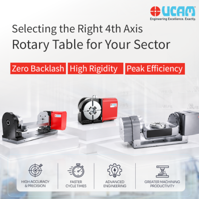
Specifying the correct trunnion architecture ensures maximum utilization of the existing machine tool envelope. UCAM’s CNC Tilting Rotary Table aligns precisely with specific shop floor part geometries.
Both standard and deep tilting configurations execute continuous 5-axis contouring when paired with compatible CNC controllers equipped with Tool Center Point Control (TCPC). Both series are constructed utilizing pre-loaded axial-radial cross-roller bearings and ultra-high torque hydraulic braking systems on the rotary and tilt mechanisms. The engineering distinction lies entirely in physical spindle clearance and payload geometry. Aligning the trunnion design with the specific workpiece profile eliminates manual setup interventions and ensures continuous, high-precision component manufacturing.
FAQs
How do I decide between a standard and a deep tilting rotary table?
Assess your part geometry and vertical machine stroke. Choose a standard table for rigid, multi-sided machining at positive angles. Specify a deep tilting table with a drop-center cradle if your components require severe negative-angle undercuts or if you need maximum Z-axis clearance for long cutting tools.
Does a deep tilting table lose rigidity due to its drop-center design?
No. UCAM deep tilting tables compensate for the shifted center of gravity using oversized cross-roller bearings and extreme braking force. For example, the URH-500DT applies 5,000 Nm of hydraulic clamping torque to the tilt axis, locking the cradle completely solid to prevent tool chatter during heavy, negative-angle roughing.
Can a standard tilting table perform 5-axis simultaneous machining?
Yes. It can execute continuous 5-axis contouring when paired with a TCPC-enabled CNC controller. The difference is purely physical: standard tables are limited by spindle housing collisions at negative angles, while deep tilting tables provide the extended clearance needed for full undercut access.


 ucam_marketing